|
|
• RS-232 Bus-pin ESD protection exceeds±15 kV using human body model (HBM)
|
• Meets or exceeds the requirements ofTIA/EIA-232-F and ITU V.28 standards
|
• Operates with 3-V to 5.5-V VCC supply
|
• Operates up to 250 kbps
|
• One driver and one receiver
|
• Low standby current: 1 μA typical
|
• External capacitors: 4 × 0.1 μF
|
• Accepts 5-V logic input with 3.3-V supply
|
• Alternative high-speed pin-compatibledevice (1 Mbps)
– SNx5C3221
|
• Automatic power-down feature automaticallydisables drivers for power savings
|
|
| CATALOG |
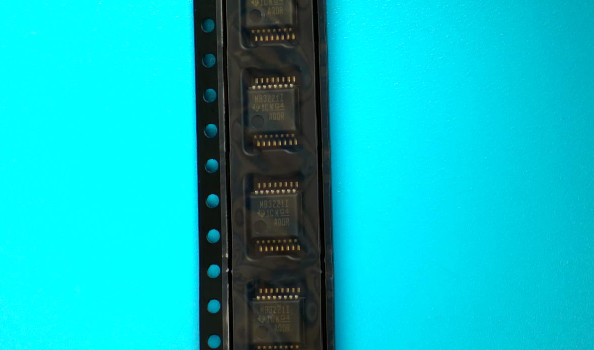
MAX3221IDBR COUNTRY OF ORIGIN
|
MAX3221IDBR PARAMETRIC INFO
|
MAX3221IDBR PACKAGE INFO
|
MAX3221IDBR MANUFACTURING INFO
|
MAX3221IDBR PACKAGING INFO
|
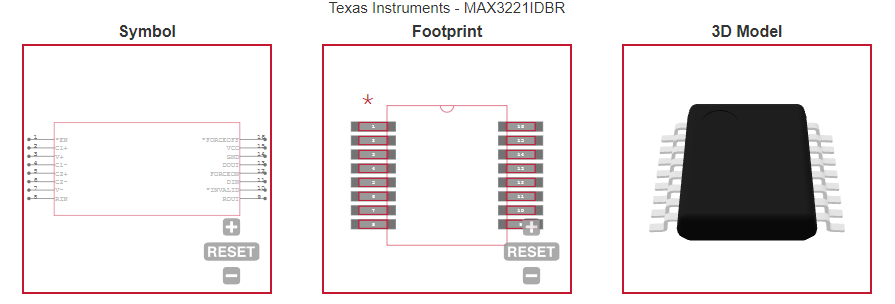
MAX3221IDBR ECAD MODELS
|
MAX3221IDBR FUNCTIONAL BLOCK DIAGRAM
|
MAX3221IDBR APPLICATIONS
|
|
| COUNTRY OF ORIGIN |
Malaysia
|
|
PARAMETRIC INFO
|
| Function |
Line Transceiver |
| Number of Transceivers |
1 |
| Number of Transmitters |
1 |
| Number of Receivers |
1 |
| Data Transmission Topology |
Point-to-Point |
| Transmitter Signal Type |
Single-Ended |
| Receiver Signal Type |
Single-Ended |
| Transmitter Communication Type |
RS-232 |
| Charge Pump |
Yes |
| Number of External Capacitors |
4 |
| Receiver Communication Type |
RS-232 |
| External Capacitor Capacitance (uF) |
0.1 |
| Power Down Mode |
Power Down |
| Interface Standards |
EIA/TIA-232-F|RS-232|V.28 |
| Number of Transmitter Enables |
1 |
| Number of Receiver Enables |
1 |
| Number of Drivers per Line |
1 |
| Number of Receivers per Line |
1 |
| Data Rate |
250Kbps |
| Driving Mode |
3-State |
| Minimum Operating Temperature (°C) |
-40 |
| Maximum Operating Temperature (°C) |
85 |
| Supplier Temperature Grade |
Industrial |
| Maximum Storage Temperature (°C) |
150 |
| Minimum Storage Temperature (°C) |
-65 |
| Power Supply Type |
Single |
| Typical Single Supply Voltage (V) |
3.3|5 |
| Minimum Single Supply Voltage (V) |
3 |
| Maximum Single Supply Voltage (V) |
5.5 |
| Maximum Supply Current (mA) |
1 |
| Isolation |
No |
|
|
PACKAGE INFO
|
| Supplier Package |
SSOP |
| Basic Package Type |
Lead-Frame SMT |
| Pin Count |
16 |
| Lead Shape |
Gull-wing |
| PCB |
16 |
| Tab |
N/R |
| Pin Pitch (mm) |
0.65 |
| Package Length (mm) |
6.5(Max) |
| Package Width (mm) |
5.6(Max) |
| Package Height (mm) |
2(Max) - 0.05(Min) |
| Package Diameter (mm) |
N/R |
| Package Overall Length (mm) |
6.5(Max) |
| Package Overall Width (mm) |
8.2(Max) |
| Package Overall Height (mm) |
2(Max) |
| Seated Plane Height (mm) |
2(Max) |
| Mounting |
Surface Mount |
| Package Weight (g) |
N/A |
| Package Material |
Plastic |
| Package Description |
Shrink Small Outline Package |
| Package Family Name |
SO |
| Jedec |
MO-150AC |
| Package Outline |
Link to Datasheet |
|
|
MANUFACTURING INFO
|
| MSL |
1 |
| Maximum Reflow Temperature (°C) |
260 |
| Reflow Solder Time (Sec) |
30 |
| Number of Reflow Cycle |
3 |
| Standard |
J-STD-020D |
| Reflow Temp. Source |
Link to Datasheet |
| Maximum Wave Temperature (°C) |
N/R |
| Wave Solder Time (Sec) |
N/R |
| Lead Finish(Plating) |
Au |
| Under Plating Material |
Pd over Ni |
| Terminal Base Material |
Cu Alloy |
| Number of Wave Cycles |
N/R |
|
|
PACKAGING INFO
|
| Packaging Suffix |
R |
| Packaging |
Tape and Reel |
| Quantity Of Packaging |
2000 |
| Reel Diameter (in) |
13 |
| Tape Pitch (mm) |
12 |
| Tape Width (mm) |
16 |
| Component Orientation |
Q1 |
| Packaging Document |
Link to Datasheet |
|
|
ECAD MODELS
|
|
|
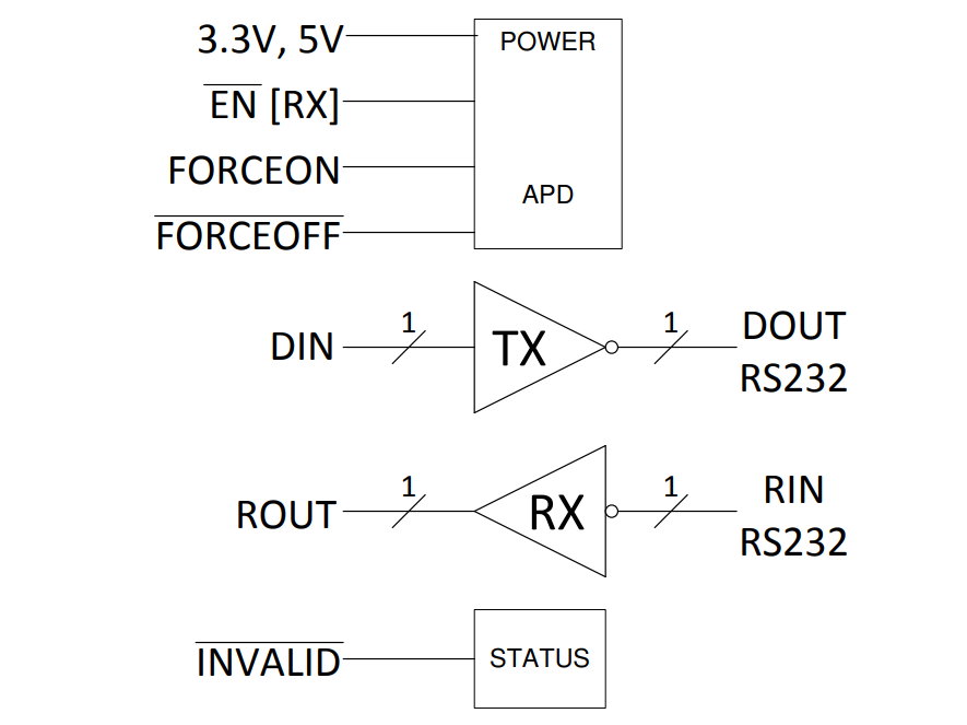
FUNCTIONAL BLOCK DIAGRAM
|
|
|
APPLICATIONS
|
• Industrial PCs
|
• Wired networking
|
• Data center and enterprise computing
|
• Battery-powered systems
|
• PDAs
|
• Notebooks
|
• Laptops
|
• Palmtop PCs
|
• Hand-held equipment
|
|