 |
|
| • Technology
0.18µm CMOS |
| • F2
MC-16FX CPU |
| • On-chip PLL clock multiplier (×1 to ×8, ×1 when PLL stop) |
| • On-chip voltage regulator
Internal voltage regulator supports a wide MCU supply voltage range (Min=2.7V), offering low power
consumption |
| • Low voltage detection function
Reset is generated when supply voltage falls below programmable reference voltage |
| • Code Security
Protects Flash Memory content from unintended read-out |
| • DMA
Automatic transfer function independent of CPU, can be assigned freely to resources |
| • Non-Maskable Interrupt (NMI |
| • Supports CAN protocol version 2.0 part A and B |
| • Full duplex USARTs (SCI/LIN) |
| • Source Clock Timers
Three independent clock timers (23-bit RC clock timer, 23-bit Main clock timer, 17-bit Sub clock timer) |
| • Hardware watchdog timer is active after reset |
| • Free-Running Timers |
| • Input Capture Units |
| • Output Compare Units |
| • Programmable Pulse Generator |
| • Stepping Motor Controller with integrated high current output drivers |
| • LCD controller with up to 4COM × 36SEG |
|
| CATALOG |
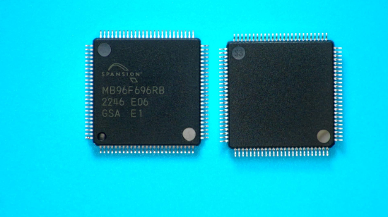
| MB96F696RBPMC-GSAE1 COUNTRY OF ORIGIN |
| MB96F696RBPMC-GSAE1 PARAMETRIC INFO |
| MB96F696RBPMC-GSAE1 PACKAGE INFO |
| MB96F696RBPMC-GSAE1 PACKAGING INFO |
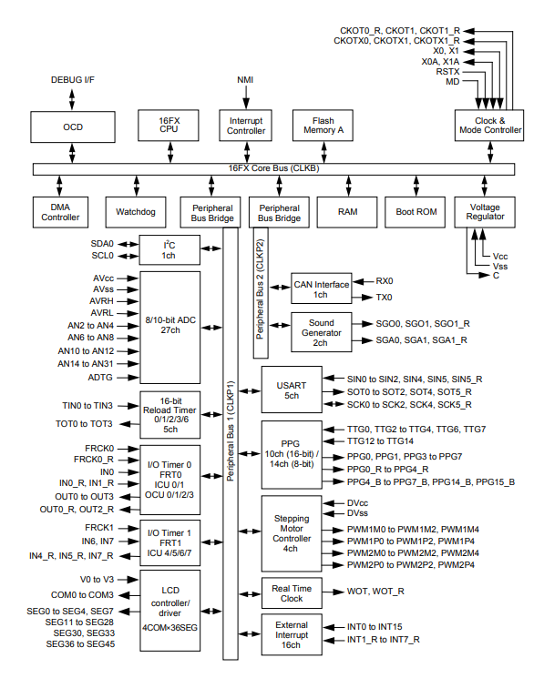
| MB96F696RBPMC-GSAE1 FUNCTONAL BLOCK DIAGRAM |
|
| COUNTRY OF ORIGIN |
| Japan |
|
| PARAMETRIC INFO |
| Data Bus Width (bit) |
16 |
| Family Name |
F2MC |
| Device Core |
F2MC-16FX |
| Instruction Set Architecture |
RISC |
| Maximum Clock Rate (MHz) |
32 |
| Program Memory Type |
Flash |
| Program Memory Size |
288.5KB |
| RAM Size |
16KB |
| Maximum CPU Frequency (MHz) |
32 |
| Number of Programmable I/Os |
77 |
| Number of Timers |
5 |
| ADC Channels |
27 |
| ADC Resolution (bit) |
10 |
| Core Architecture |
F2MC |
| Number of ADCs |
Single |
| PWM |
8 |
| Watchdog |
1 |
| LCD Segments |
144 |
| Special Features |
CAN Controller,LCD Controller |
| Interface Type |
CAN/I2C/USART |
| Programmability |
Yes |
| SPI |
0 |
| I2C |
1 |
| I2S |
0 |
| UART |
0 |
| USART |
5 |
| CAN |
1 |
| USB |
0 |
| Ethernet |
0 |
| Maximum Power Dissipation (mW) |
333 |
| Minimum Operating Supply Voltage (V) |
2.7 |
| Typical Operating Supply Voltage (V) |
3.3|5 |
| Maximum Operating Supply Voltage (V) |
5.5 |
| Minimum Operating Temperature (°C) |
-40 |
| Maximum Operating Temperature (°C) |
105 |
| Temperature Flag |
Opr |
| Operating Supply Voltage (V) |
3.3|5 |
| Maximum Storage Temperature (°C) |
150 |
| Minimum Storage Temperature (°C) |
-55 |
|
| |
| PACKAGE INFO |
| Supplier Package |
LQFP |
| Pin Count |
100 |
| PCB |
100 |
| Tab |
N/R |
| Package Length (mm) |
14 |
| Package Width (mm) |
14 |
| Package Height (mm) |
1.4 |
| Package Diameter (mm) |
N/R |
| Mounting |
Surface Mount |
| Package Outline |
Link to Datasheet |
|
| |
| PACKAGING INFO |
| Packaging |
Tray |
| Quantity Of Packaging |
90(Min) |
| Packaging Document |
Link to Datasheet |
|
| |
| FUNCTONAL BLOCK DIAGRAM |
 |
|